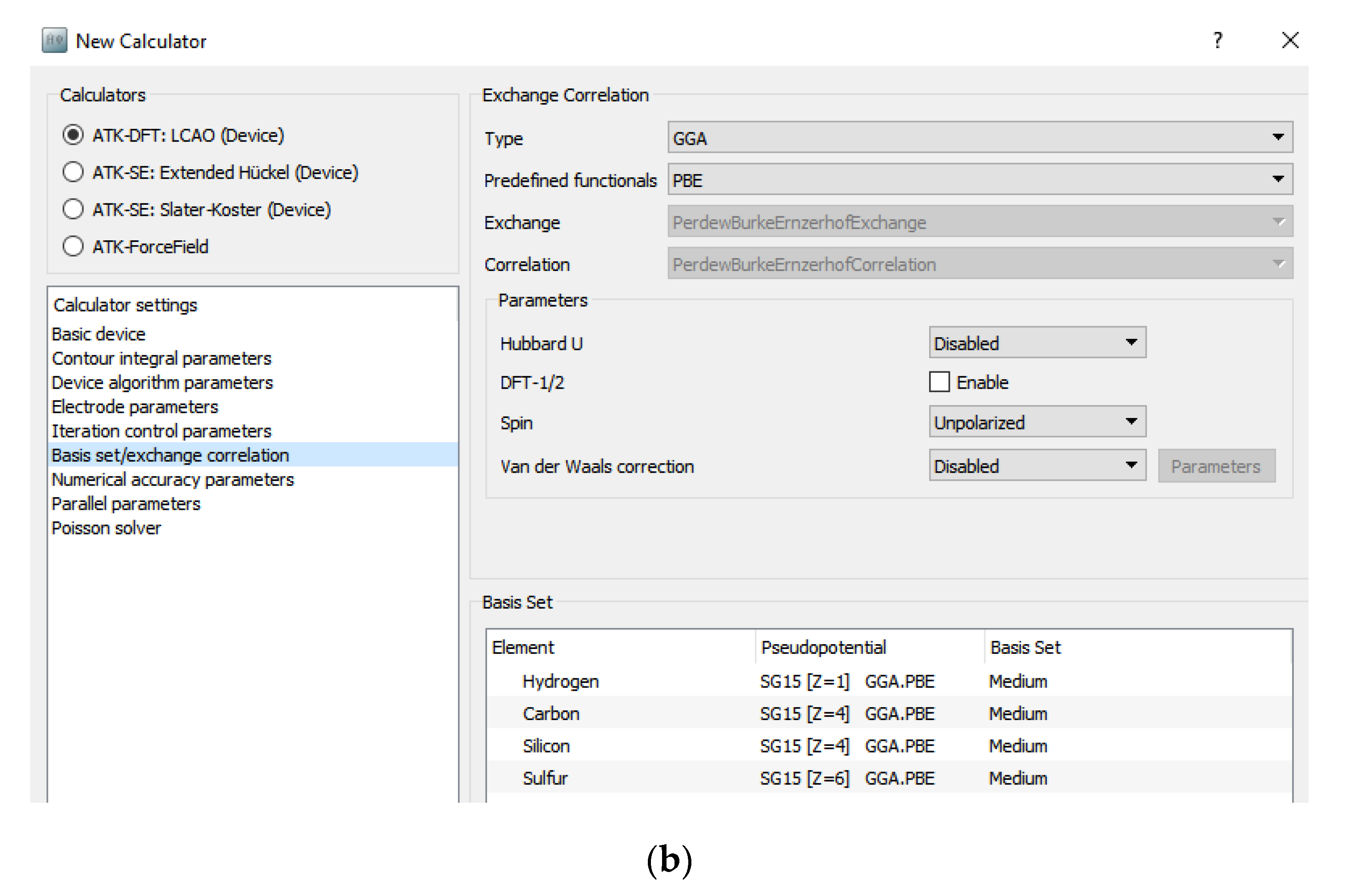

- #Quantumwise setting deice calculation parameters how to
- #Quantumwise setting deice calculation parameters pdf
Therefore, you can keep the NiSi side much shorter than the Si side to save computational time. Note The screening length of a metal is much smaller that that of a semiconductor, only few atomic layers. A good way to check if your system is large enough is to plot the Electrostatic Difference Potential along the device (see below). This means that you will need a silicon region of about 30 Å to 100 Å wide. Throughout this tutorial you will use doping concentrations ranging from 1019 cm -3 to 1020 cm -3. 119) as a function of the doping concentration N.Ĥ For the purpose of your simulations you need to ensure that the silicon part in the central region is larger than the width of depletion layer.

The plot below shows typical values of W D for a metal-semiconductor junction (as reported in pag. The width of the depletion layer depends on: the dielectric constant of the semiconductor the doping concentration (number of carriers) the potential barrier at the interface the applied voltage. However, you need to be very careful about another quantity: the width of the depletion layer, usually denoted as W D, which is related to the screening length of the semiconductor.


The screening region What should be your doping concentration? In principle, you can use the experimental one. Do not modify the electrode lengths but increase the size of the central region on the left and right side by 100% compared to the size of left and right electrodes, respectively. Go to Device Tools Device From Bulk to create the device configuration from the bulk configuration. Use Add From Files to add the newly downloaded interface structure to the Stash.
#Quantumwise setting deice calculation parameters how to
2 2 Note You can learn how to create an interface from the tutorials Building a Si-Si3N4 Interface, Graphene Nickel interface and Building an interface between Ag(100) and Au(111).ģ 3. The latter can be downloaded here: Interface.py. The first thing you have to do is to create a device configuration starting from the LDA-optimized NiSi -Si bulk configuration of the interface. Create a new empty project and open the Builder (icon ). In particular you will: create the device to calculate the transport properties of such interface learn how to add the proper doping to simulate a real device analyze the results in terms of electrostatic potentials, electron density and density of states, by using the tools included in Virtual NanoLab.
#Quantumwise setting deice calculation parameters pdf
1 Table of Contents Table of Contents NiSi2 Si interface Create the NiSi2/Si device The screening region Increase the length of the central region Set-up the calculation for the undoped device Dope the device Analysis of the results Electrostatic difference potential Electron Difference Density Electron density difference (doped - undoped) 3D Analysis 1D Analysis Density of states (DOS) analysis Projected Local Density Of States Device Density Of States Finite-bias calculations Set up the IV curve calculation Transmission spectrum convergence IV curve object analysis Post analysis of finite-bias calculations Analysis of a single self-consistent configuration Analysis of multiple self-consistent configurations Analysis of the IV curve ReferencesĢ QuantumWise QuantumWise is now part of Synopsys TRY IT! COMPANY CONTACT Docs» Tutorials» Semiconductors» NiSi Si interface 2 NiSi Si interface 2 Downloads & Links PDF version Interface.py edp_macro_avg.py long_ndoped_e19_ivcurve.py loop.py l_ndoped_e19_edp.py l_ndoped_e19_ddos.py Basic VNL and ATK Tutorial ATK Reference Manual In this tutorial you will study a doped NiSi2-Si interface and its electronic transport properties.


 0 kommentar(er)
